|
OUT
LINE OF CONSTRUCTION
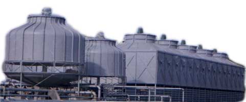
The cooling tower si shaped like a cylinder with an axial
flow fan mounted on top to give vertical discharge. This
tower is very ideal for cooling efficiency and space economy.
CASING
(F. R. P.)
The tower casing has been manufactured from F. R. P. which
gives sufficient structural strength to withstand high wind
velocity and vibrations. It is resistant to local impact
and even if damage is sustained it can be repaired locally
very easily.
WATER
BASIN (F. R. P.)
The water basin is made of F. R. P. like casing it is bowl-shaped
with a cylindrical auxiliary Suction tank at the bottom.
A drain is provided to facilitate the removal of accumulated
dirt from the bottom of the tank.
SUPPORTING
STRUCTURE
The supporting frame work for the casing and basin will
be of hot dip galvanised steel or epoxy painted steel as
per the preference of the client.
FILLS
The evaporative media in this tower; fills, are specially
designed pre evaporative fills. They have excellent heat
exchange efficiency and corrosion resistance.
SPRAY
SYSTEM
The spray system is designed to achieve maximum water surface
area per unit volume of tower by spraying the water through
specially designed spray nozzles made from brass. The pipe
headers and branch arms are of galvanised steel. This spray
system eliminates rotating type sprinkler system and thus
provides low maintenance.
FAN
The specially designed axial flow type fan is used for cooling
tower. These fans deliver large air volumes with low noise
level at high efficiency. This is made of special aluminium
allloy and has four blades.
For
efficiency and economy, install longer lasting, corrosion
proof ANUCOOL F. R. P. Cooling Tower for central air-conditioning
palnts and industrial water Cooling System.
|